服务热线< img border="0" src="http://wpa.qq.com/pa?p=2:2907815691:51" alt="免费在线咨询" title="免费在线咨询"/>
13636657709
服务热线< img border="0" src="http://wpa.qq.com/pa?p=2:2907815691:51" alt="免费在线咨询" title="免费在线咨询"/>
13636657709
|
Size |
6 | ||
|
Weight |
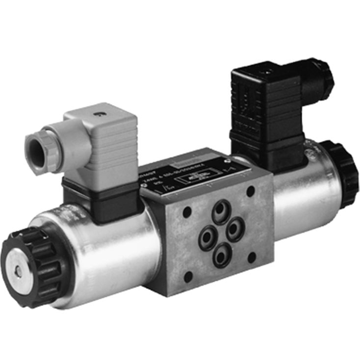
Valve with one solenoid |
kg |
1.2 |
|
Valve with two solenoids |
kg |
1.6 | |
|
Installation position |
any | ||
|
Ambient temperature ranges (NBR seals) |
°C |
-30 … +50 | |
|
Ambient temperature ranges (FKM seals) |
°C |
-20 … +70 | |
|
MTTFD values according to EN ISO 13849 1) |
Years |
150 | |
|
Admissible shock and vibration loads |
see data sheet 08012 | ||
| 1) | For further details, see data sheet 08012 |
|
Size |
6 | |||
|
Maximum operating pressure |
Port P |
bar |
315 | |
|
Anschluss A |
bar |
315 | ||
|
Port B |
bar |
315 | ||
|
Port T |
with DC solenoid |
bar |
210 | |
|
with AC solenoid |
bar |
160 | ||
|
Maximum flow |
l/min |
50 | ||
|
Hydraulic fluid |
see table | |||
|
Hydraulic fluid temperature range (NBR seals) |
°C |
-30 … +80 | ||
|
Hydraulic fluid temperature range (FKM seals) |
°C |
-20 … +80 | ||
|
Viscosity range |
mm²/s |
2.8 … 500 | ||
|
Maximum admissible degree of contamination of the hydraulic fluid 1) |
Class 20/18/15 according to ISO 4406 (c) | |||
| 1) | The cleanliness classes specified for the components must be adhered to in hydraulic systems. Effective filtration prevents faults and simultaneously increases the life cycle of the components. For the selection of the filters, see www.boschrexroth.com/filter. |
|
Voltage type |
Direct voltage | AC voltage 50/60 Hz | ||
|
Available voltages 1) |
V |
12 / 24 / 96 / 205 | 110 / 230 | |
|
Voltage tolerance |
Nominal voltage |
% |
± 10 | ± 10 |
|
Power consumption |
W |
30 | - | |
|
Holding power |
VA |
- | 50 | |
|
Switch-on power |
VA |
- | 220 | |
|
Duty cycle |
% |
100 | 100 | |
|
Switching time according to ISO 6403 2) |
On |
ms |
20 … 45 | 10 … 20 |
|
Off |
ms |
10 … 25 | 15 … 40 | |
|
Maximum switching frequency |
1/h |
15000 | 7200 | |
|
Maximum coil temperature 3) |
°C |
150 | 180 | |
|
Protection class according to DIN EN 60529 |
IP65 (with mating connector mounted and locked) | |||
| 1) | Special voltages available upon request |
| 2) | The switching times were determined at a hydraulic fluid temperature of 40 °C and a viscosity of 46 mm2/s. Deviating hydraulic fluid temperatures can result in different switching times. Switching times change dependent on operating time and application conditions. |
| 3) | Due to the surface temperatures of the solenoid coils, the standards ISO 13732-1 and EN 982 need to be adhered to!The specified surface temperature in AC solenoids is valid for fault-free operation. In the error case (e. g. blocking of the control spool), the surface temperature may increase above 180 °C [356 °F]. Thus, the system must be checked for possible dangers considering the flash point (see table Hydraulic fluids).As fuse protection, circuit breakers (see table Circuit breakers) must be used, unless the creation of an ignitable atmosphere can be excluded in a different way. Thus, the surface temperature can – in the error case – be limited to maximally 220 °C [428 °F].Within a time interval of 0.6 s, the tripping current must be 8 to 10 times the nominal power supply (tripping characteristics “K”).The required non-tripping current of the fuse must not fall below the value I1 (see table Circuit breakers with tripping characteristics “K”). The maximum tripping current of the fuse must not exceed the value I2 (see table Circuit breakers with tripping characteristics “K”).The temperature dependence of the tripping behavior of the circuit breakers has to be observed according to the manufacturer's specifications. |
Actuation of the manual override is only possible up to a tank pressure of approx. 50 bar. Avoid damage to the bore of the manual override! (Special tool for the operation, separate order, material no. R900024943). When the manual override is blocked, the actuation of the solenoid must be prevented! The simultaneous actuation of the solenoids must be prevented!
AC solenoids can be used for 2 or 3 mains; e.g. solenoid type W110 for: 110 V, 50 Hz; 110 V, 60 Hz; 120 V, 60 Hz
Circuit breakers with tripping characteristics K according to EN 60898-1 (VDE 0641-11), EN 60947-2 (VDE 0660-101), IEC 60898 and IEC 60947-2
|
Valve nominal voltage |
Nominal power supply |
Recommended fuse rated current |
|
|
50 Hz |
60 Hz |
||
|
24 |
2 |
1,5 |
3 |
|
42
|
1,26 |
0,98 |
2 |
|
48 |
1 |
0,95 |
1,6 |
|
100 |
0,56 |
0,5 |
1 |
|
110 |
0,52 |
0,45 |
0,75 |
|
115
|
0,45 |
0,37 |
0,75 |
|
127 |
0,42 |
0,32 |
0,75 |
|
200 |
0,29 |
0,26 |
0,5 |
|
220 |
0,27
|
0,23 |
0,5 |
|
230 |
0,23 |
0,17 |
0,5 |
|
240 |
0,23 |
0,19 |
0,5 |
When establishing the electrical connection, the protective earthing conductor (PE ⊥) must be connected correctly.
The electric connection is realized via a 4-pole mating connector (separate order) with connection thread M12 x 1.
|
Connection voltage (DC voltage) |
V |
24 | ||
|
Voltage tolerance (connection voltage) |
+30 %/-15 % | |||
|
Admissible residual ripple |
% |
≤ 10 | ||
|
Max. load capacity |
mA |
400 | ||
|
Switching outputs 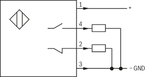
|
PNP transistor outputs, load between switching outputs and GND | |||
|
Pinout 
|
1 |
V |
24 | |
|
2, 4 |
Switching output |
mA |
400 | |
|
3 |
Earthing (GND) |
V |
0 | |
For applications outside these parameters, please consult us!
|
Ordering code |
Mains |
|
W110 |
110 V, 50 Hz |
|
110 V, 60 Hz |
|
|
120 V, 60 Hz |
|
|
W 230 |
230 V, 50 Hz |
|
230 V, 60 Hz |
|
Hydraulic fluid |
Classification |
Suitable sealing materials |
Standards |
|
|
Mineral oils and related hydrocarbons |
HL, HLP, HLPD, HVLP, HVLPD |
NBR, FKM |
DIN 51524 |
|
|
Environmentally compatible |
Insoluble in water |
HETG |
NBR, FKM |
ISO 15380 |
|
HEES |
FKM |
|||
|
Soluble in water |
HEPG |
FKM |
ISO 15380 |
|
|
Containing water |
HFC |
NBR |
ISO 12922 |
|