服务热线< img border="0" src="http://wpa.qq.com/pa?p=2:2907815691:51" alt="免费在线咨询" title="免费在线咨询"/>
13636657709
服务热线< img border="0" src="http://wpa.qq.com/pa?p=2:2907815691:51" alt="免费在线咨询" title="免费在线咨询"/>
13636657709
|
Size |
4 | 5 | 8 | 11 | 14 | 16 | 19 | 22 | ||||
|
Series |
Series 1x | |||||||||||
|
Displacement |
Vg |
cm³ |
4 | 5.5 | 8 | 11 | 14 | 16 | 19 | 22.5 | ||
|
Pressure at suction port S |
absolute |
pe |
bar |
0.7 ... 3 | ||||||||
|
Maximum continuous pressure |
p1 |
bar |
190 | 190 | 190 | 190 | 190 | 190 | 180 | 170 | ||
|
Maximum intermittent pressure |
p2 |
bar |
210 | 210 | 210 | 210 | 210 | 210 | 200 | 190 | ||
|
Maximum pressure peaks |
p3 |
bar |
230 | 230 | 230 | 230 | 230 | 230 | 220 | 210 | ||
|
Minimum speed at |
ν = 12 mm²/s |
p < 100 bar |
nmin |
rpm |
700 | 700 | 700 | 700 | 700 | 700 | 700 | 700 |
|
p = 100 … 180 bar |
nmin |
rpm |
1200 | 1200 | 1000 | 1000 | 800 | 800 | 800 | 800 | ||
|
p = 180 bar … p2 |
nmin |
rpm |
1400 | 1400 | 1400 | 1200 | 1000 | 1000 | 1000 | 1000 | ||
|
ν = 25 mm²/s |
at p2 |
nmin |
rpm |
700 | 700 | 700 | 700 | 700 | 700 | 700 | 700 | |
|
Maximum speed |
at p2 |
nmax |
rpm |
3500 | 3500 | 3500 | 3500 | 3000 | 3000 | 3000 | 2500 | |
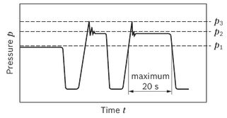
| p1: Continuous pressure max. | |
| p2: Intermittent pressure max. | |
| p3: Pressure peaks max. |
|
Determining the operating characteristics |
||
|
Flow |

|
[l/min] |
|
Torque |

|
[Nm] |
|
Power |

|
[kW] |
|
Key |
|
|
Vg |
Displacement per revolution [cm3] |
|
Δp |
Differential pressure [bar] |
|
n |
Rotational speed [rpm] |
|
ηv |
Volumetric efficiency |
|
ηhm |
Hydraulic-mechanical efficiency |
|
ηt |
Total efficiency (ηt = ηv • ηhm) |

You can find diagrams for a rough calculation in chapter "Diagrams / Characteristic curves".
|
Weight |
m |
kg |
See chapter Dimensions |
|
Installation position |
No restrictions |
||
|
Mounting type |
Flange or through-bolting with spigot |
||
|
Line connections |
See chapter Dimensions |
||
|
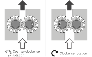
Direction of rotation, viewed on drive shaft |
Clockwise or counter-clockwise, the pump may only be driven in the direction indicated |
||
|
Drive shaft loading |
Axial and radial forces only after consultation |
||
|
Ambient temperature range |
ϑ |
°C |
-30 to +80 with NBR seals (NBR = nitrile rubber) |
|
-20 to +110 with FKM seals (FKM = fluoroelastomer) |
|||
The external gear unit is designed for operation with mineral oil according to DIN 51524, 1-3. Under higher load, however, Bosch Rexroth recommends at least HLP compliant with DIN 51524 Part 2.
Application instructions and requirements for hydraulic fluids should be taken from the following data sheets before the start of project planning:
Other hydraulic fluids on request.
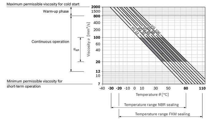
The hydraulic fluid should be selected such that the operating viscosity in the operating temperature range is within the optimum range (vopt see selection diagram).
|
Viscosity range |
|
|
Permissible in continuous operation |
ν = 12 … 800 mm²/s |
|
Recommended in continuous operation |
νopt = 20 … 100 mm²/s |
|
Permissible for cold start |
νmax ≤ 2000 mm²/s |
|
Temperature range |
|
|
With NBR seals (NBR = nitrile rubber) |
ϑ = -30 °C … +80 °C |
|
With FKM seals (FKM = fluoroelastomer) |
ϑ = -20 °C … +110 °C |
Observe the instructions for the filtration of the hydraulic fluid (see chapter Project planning information).
The dimensional drawings in the chapter Dimensions represent pumps for clockwise rotation. The position of the drive shaft or the position of suction and pressure port changes for counter-clockwise rotation.


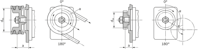
For V-belt or gear wheel drives, please contact us specifying the application and mounting conditions (dimensions a, dm, dw and angle α). For helical toothed gear drives, details of the helix angle β are also required.
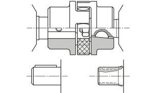
|
Drive shaft |
Front cover |
Mmax |
Size |
p2 max |
|
|
Code |
Designation |
Code |
Nm |
bar |
|
| F | DIN 5482 B17 × 14 | B, P, N | 100 | 4 … 16 | 210 |
| 19 | 200 | ||||
| 22 | 190 | ||||
| R | SAE J744 16-4 9T | R | 110 | 4 … 16 | 210 |
| 19 | 200 | ||||
| 22 | 190 | ||||
|
Drive shaft |
Front cover |
Mmax |
Size |
p2 max |
|
Code |
Code |
Nm |
bar |
|
| N | T | 52 | 4 … 14 | 210 |
| 16 | 180 | |||
| 19 | 150 | |||
| 22 | 130 |
|
Drive shaft |
Front cover |
Mmax |
Size |
p2 max |
|
|
Code |
Type |
Code |
Nm |
bar |
|
| C | 1 : 5 | B, P, N | 130 | 4 … 16 | 210 |
| 19 | 200 | ||||
| 22 | 190 | ||||
| H | 1 : 8 | O | 4 … 16 | 210 | |
| 19 | 200 | ||||
| 22 | 190 | ||||
|
Drive shaft |
Front cover |
Mmax |
Size |
p2 max |
|
|
Code |
Designation |
Code |
Nm |
bar |
|
| Q | SAE J744 16-1 A | R | 55 | 4 … 14 | 210 |
| 16 | 190 | ||||
| 19 | 165 | ||||
| 22 | 140 | ||||