服务热线< img border="0" src="http://wpa.qq.com/pa?p=2:2907815691:51" alt="免费在线咨询" title="免费在线咨询"/>
13636657709
服务热线< img border="0" src="http://wpa.qq.com/pa?p=2:2907815691:51" alt="免费在线咨询" title="免费在线咨询"/>
13636657709
For applications outside these parameters, please consult us!
|
Size |
40 | 71 | 125 | 180 | 250 | 355 | ||||
|
Displacement |
Vg max |
cm³ |
40 | 71 | 125 | 180 | 250 | 355 | ||
|
Speed 1) |
maximum at Vg max |
no |
rpm |
2600 | 2200 | 1800 | 1900 | 1700 | ||
|
maximum at Vg maxand HFC fluids |
no |
rpm |
2200 | 1800 | 1500 | |||||
|
Minimum speed 2) |
nmin |
rpm |
200 | |||||||
|
Min. Speed at HFC-fluids |
with ν = 25 mm2/s |
nmin |
rpm |
750 | 850 | 600 | 550 | 450 | ||
|
Max. flow (displacement) |
at n0 and Vg max |
qv0 max |
l/min |
104 | 156 | 225 | 324 | 450 | 533 | |
|
with nE = 1500 min-1and Vg max |
qvE max |
l/min |
60 | 107 | 186 | 270 | 375 | 533 | ||
|
Max. power (Δp = 350 bar) |
at n0 and Vg max |
P0 max |
kW |
61 | 91 | 131 | 189 | 263 | 311 | |
|
with nE = 1500 min-1and Vg max |
PE max |
kW |
35 | 62 | 109 | 158 | 219 | 311 | ||
|
Max. torque (Δp = 350 bar) |
Tmax |
Nm |
223 | 395 | 696 | 1002 | 1391 | 1976 | ||
|
Maximum permissible drive torque |
Fitting key |
Ttotal |
Nm |
380 | 700 | 1392 | 1400 | 2300 | 3557 | |
|
Splined shaft S overall torque |
Ttotal |
Nm |
446 | 790 | 1392 | 2004 | 2782 | 3952 | ||
|
Max. admissible through-drive torque |
TD |
Nm |
223 | 395 | 696 | 1002 | 1391 | 1976 | ||
|
Drive shaft load |

|
max. admissible axial force |
Fax max |
N |
600 | 800 | 1000 | 1400 | 1800 | 2000 |
|
max. admissible radial force 3) |
Fq |
N |
1000 | 1200 | 1600 | 2000 | 2200 | |||
|
Weight without filling quantity |
m |
kg |
39 | 53 | 88 | 102 | 184 | 207 | ||
|
Moment of inertia around drive axis |
kg·m² |
0.0049 | 0.0121 | 0.03 | 0.055 | 0.0959 | 0.19 | |||
|
Filling quantity of the housing |
l |
2 | 2.5 | 5 | 4 | 10 | 8 | |||
|
Maximum admissible operating pressure 4) |
pmax |
bar |
350 | |||||||
|
Operating pressure, min. (without load) |
pmin |
bar |
≥ 20 | |||||||
|
Admissible inlet pressure |
p |
bar |
0.8 ... 30 | |||||||
|
Hydraulic fluid |
Mineral oil (HL, HLP) according to DIN 51524; HFC optional | |||||||||
|
Hydraulic fluid temperature range |
ϑ |
°C |
-20 … +70 | |||||||
|
Maximum admissible degree of contamination of the hydraulic fluid according to ISO 4406 |
Class 18/16/13 (for particle size ≤ 4/6/14 μm) | |||||||||
| 1) | The values are applicable at an absolute pressure of 1 bar at the suction opening S. With a reduction of the displacement or an increase in the inlet pressure, the speed can be increased according to the following characteristic curve. With a reduced inlet pressure, the speed is to be reduced. |
| 2) | Does not apply to HFC fluid, formula for determination of the minimum speed see below |
| 3) | In case of higher radial forces, please consult us. Not applicable for use of HFC fluids. |
| 4) | When using HFC fluids, also see data sheet 92053. |
| 1) | At SYHDFEN, the minimum speed can be determined by means of the derating function. |
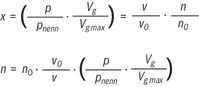
Example 1:
A4VSO125 may be operated at ν = 16 mm2/s
as of n = 1328 rpm with nominal load
Example 2:
the admissible load for A4VSO250
is n = 500 rpm and 10 mm2/s
x = 10/25*500/550 = 0.364 (= 127 bar at Vgmax)
|
Size |
40 | 71 | 125 | 180 | 250 | 355 | |||
|
Operating voltage |
UB |
24 VDC +40 % –5 % | |||||||
|
Operating range (short-time operation) |
Upper limit value |
UB(t)max |
V |
35 | |||||
|
Lower limit value |
UB(t)min |
V |
21 | ||||||
|
Current consumption (in static control operation) |
Rated current |
Inom |
A |
0.6 | |||||
|
Maximum current |
Imax |
A |
1.25 | ||||||
|
Inputs |
Actual pressure value input X1; |
U or I |
Determination by means of ordering code | ||||||
|
Analog current inputs, load |
RB |
100 Ω | |||||||
|
Analog voltage inputs |
RE |
≥ 50 kΩ | |||||||
|
Digital inputs |
Logic 0 |
≤ 0,6 V | |||||||
|
Logic 1 |
≥ 21 V | ||||||||
|
Outputs |
pactual / UOUT1 |
UO 1) |
0 ... 10 V | ||||||
|
Imax 1) |
1,5 mA | ||||||||
|
αactual / UOUT2 |
UO 1) |
± 10 V | |||||||
|
Imax 1) |
1,5 mA | ||||||||
|
Digital outputs |
Logic 0 |
Ua < 1 V | |||||||
|
Logic 1 |
Ua ≥ UB – 5 V; 10 mA (short-circuit-proof) | ||||||||
|
Ambient temperature range at the pump |
ϑ |
°C |
0 … 60 | ||||||
|
Storage temperature range (pump + electronics) |
ϑ |
°C |
0 … 70 | ||||||
|
Electronics design |
Integrated in the pilot valve (OBE) | ||||||||
|
Type of protection according to EN 60529 |
Pump incl. pilot valve |
IP65 with mounted and locked plug-in connectors | |||||||
|
Power limitation |
optional | ||||||||
| 1) | With SYDFEC, the outputs are parameterizable, for the condition as supplied, see electrical connection |
Notice:
For information on the environment simulation testing for the areas of EMC (electro-magnetic compatibility), climate and mechanical load, see data sheet 30030-U.
Bearing flushing
With the following operating conditions, bearing flushing is necessary for safe continuous operation:
With vertical installation (drive shaft upwards), bearing flushing is recommended for lubrication of the front bearing and the shaft seal ring.
The bearing is flushed using port "U" in the area of the front flange of the variable displacement pump. The flushing fluid flows through the front bearing and exits with the pump leakage at the leakage connection.
For the individual sizes, the following flushing quantities are recommended:
|
Size |
40 | 71 | 125 | 180 | 250 | 355 | ||
|
recommended flushing quantity |
qSp |
l/min |
3 | 4 | 5 | 7 | 10 | 15 |
The specified flushing quantities result in a pressure differential between port "U” (including fitting) and the leakage chamber of approx. 2 bar (series 1) and approx. 3 bar (series 3).
When using the external bearing flushing, the throttle screw in port U has to be screwed-in to the stop.
Leakage pressure
The admissible leakage pressure (housing pressure) depends on the speed (see diagram).
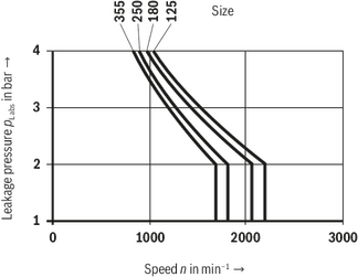
Max. leakage pressure (housing pressure)
pL abs max = 4 bar absolute
These specifications are guidelines; under special operating conditions, a limitation may become necessary.
Flow direction
S → B
Notes:
|
Swivel angle control |
Pressure control 1) |
|
|
Linearity tolerance |
≤ 1.0 % |
≤ 1.5 % |
|
Temperature error |
≤ 0.5 % / 10 K |
≤ 0.5 % / 10 K |
|
Hysteresis |
≤ 0.2 % |
≤ 0.2 % |
|
Repetition accuracy |
≤ 0.2 % |
≤ 0.2 % |
| 1) | Without considering the pump pulsation. |
|
Admissible drive and through-drive torques |
||||||||
|
Size |
40 |
71 |
125 |
180 |
250 |
355 |
||
|
Splined shaft |
||||||||
|
Maximally admissible total drive torque at the shaft of pump 1 (pump 1 + pump 2) |
TGes max |
[Nm] |
446 |
790 |
1392 |
2004 |
2782 |
3952 |
|
A Admissible through-drive torque |
TD1 max |
[Nm] |
223 |
395 |
696 |
1002 |
1391 |
1976 |
|
TD2 max |
[Nm] |
223 |
395 |
696 |
1002 |
1391 |
1976 |
|
|
B Admissible through-drive torque |
TD1 max |
[Nm] |
223 |
395 |
696 |
1002 |
1391 |
1976 |
|
TD2 max |
[Nm] |
223 |
395 |
696 |
1002 |
1391 |
1976 |
|
|
Fitting key |
||||||||
|
Maximally admissible total drive torque at the shaft of pump 1 (pump 1 + pump 2) |
TGes max |
[Nm] |
380 |
700 |
1392 |
1400 |
2300 |
3557 |
|
A Admissible through-drive torque |
TD1 max |
[Nm] |
223 |
395 |
696 |
1002 |
1391 |
1976 |
|
TD2 max |
[Nm] |
157 |
305 |
696 |
398 |
909 |
1581 |
|
|
B Admissible through-drive torque |
TD1 max |
[Nm] |
157 |
305 |
696 |
398 |
909 |
1581 |
|
TD2 max |
[Nm] |
223 |
395 |
696 |
1002 |
1391 |
1976 |
|

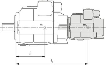
related to mounting flange of the main pump

|
Tm [Nm] |
Admissible mass torque |
|
m1, m2 [kg] |
Weight of the pump |
|
l1, l2 [mm] |
Distance of the center of gravity |
|
Size |
40 |
71 |
125 |
180 |
250 |
355 |
||
|
Admissible mass torque |
Tm zul. |
Nm |
1800 |
2000 |
4200 |
4200 |
9300 |
9300 |
|
Admissible mass torque with dynamic mass acceleration of 10 g = 98.1 m/sec2 |
Tm zul. |
Nm |
180 |
200 |
420 |
420 |
930 |
930 |
|
Weight (SYHDFE or A4VSO...DR) |
m |
kg |
39 |
53 |
88 |
102 |
184 |
207 |
|
Distance of the center of gravity |
l1 |
mm |
120 |
140 |
170 |
180 |
210 |
220 |
Tightening torques: